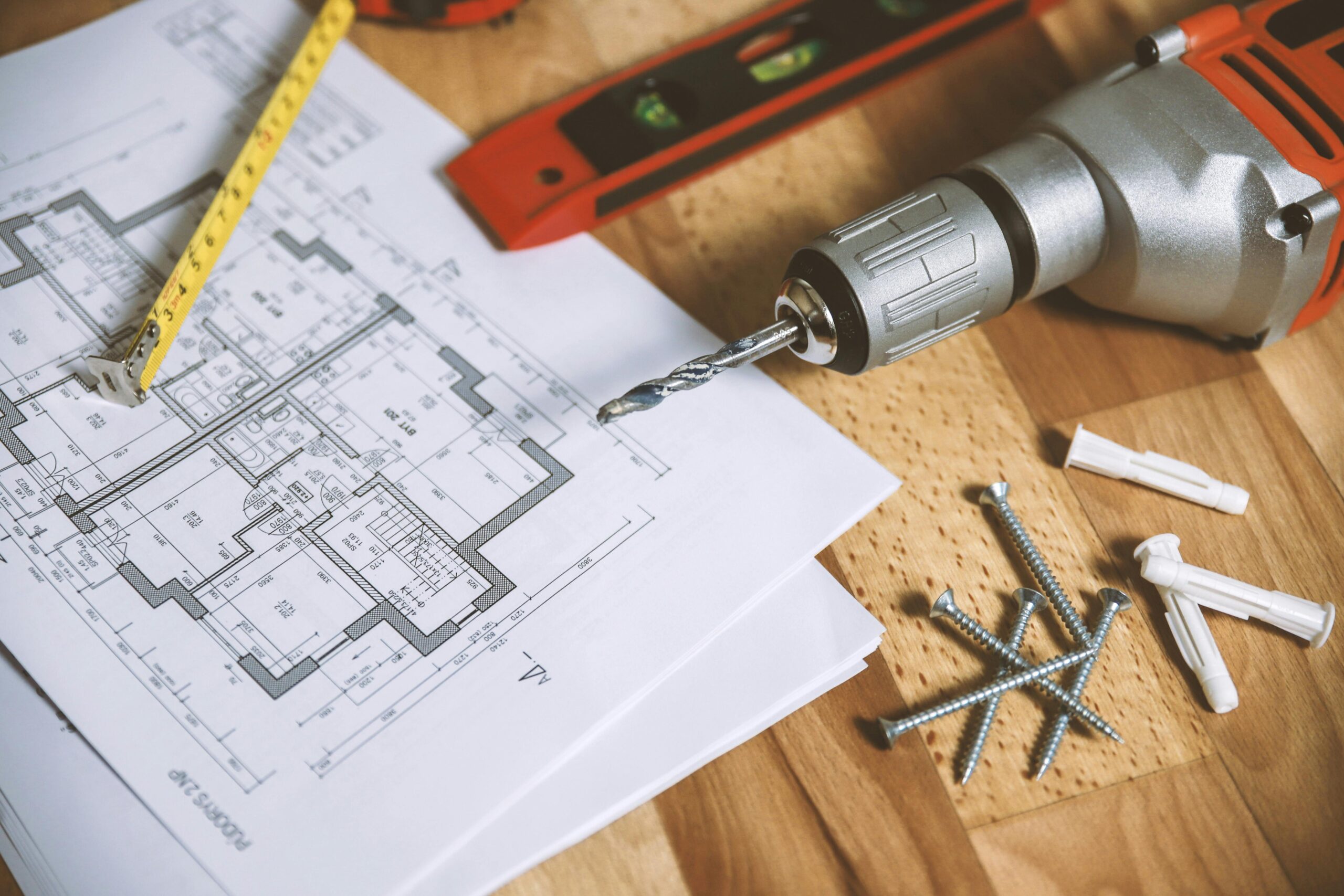
Construction blueprints can appear intimidating at first glance, filled with unfamiliar symbols, measurements, and technical terminology. However, understanding these architectural drawings is crucial for homeowners who want to effectively communicate with contractors or manage their own renovation projects. This guide will demystify the essential elements of construction plans, including scale interpretation, common symbols, elevation views, and floor plan components, equipping you with the knowledge to confidently review your next building project’s documentation.
Understanding Blueprint Basics
Construction blueprints are technical drawings that serve as the primary communication tool between architects, engineers, contractors, and homeowners. They provide detailed instructions for how a structure should be built or modified. When first learning how to read blueprints construction plans, it’s important to understand they typically consist of multiple pages representing different aspects of the project. A complete set usually includes floor plans, elevations, sections, electrical layouts, plumbing diagrams, and foundation plans. Each page works together to create a comprehensive guide for the construction team.
The title block is your starting point when examining any blueprint. Located usually in the bottom right corner, it contains crucial information including the project name, architect’s contact details, date of creation, scale, and revision history. Many homeowners overlook this section, but it provides essential context about when and by whom the plans were created, helping you determine if you’re looking at the most current version.
Deciphering Scales and Measurements
Scale is one of the most fundamental concepts when interpreting blueprints. Construction drawings are rarely produced at actual size, instead being scaled down to fit on standard paper sizes. Common residential blueprint scales include 1/4 inch = 1 foot, meaning that every quarter inch on the drawing represents one foot of the actual structure. Some detailed components might use a different scale, such as 1/2 inch = 1 foot for intricate areas like kitchens or bathrooms.
Most blueprints include a graphic scale bar that allows you to measure distances directly on the drawing. This tool is invaluable when you need to determine actual dimensions without calculating conversions. Remember that measurements on blueprints are typically shown to the nearest 1/8 inch, reflecting the precision needed in construction. If you’re uncertain about any measurements, don’t hesitate to reach out to professionals on platforms like AskHomey where experts can provide clarification on interpreting complex blueprint dimensions.
Understanding Architectural Drawings Symbols
Understanding architectural drawings symbols is crucial for blueprint interpretation. These standardized markings create a universal language that communicates specific building elements, materials, and features without requiring extensive written notes. Wall symbols are represented by parallel lines with the space between them indicating the wall thickness. Doors appear as arcs showing their swing direction, while windows are typically shown as breaks in wall lines with thin lines representing the glass.
Electrical symbols denote the locations of outlets, switches, lights, and other electrical components. Plumbing fixtures like sinks, toilets, and bathtubs have their own distinctive symbols. HVAC components, including vents, return air grilles, and thermostats, are also marked with specific symbols. While these symbols may vary slightly between different architectural firms, most follow industry standards. Taking time to familiarize yourself with these common markings will dramatically improve your blueprint reading skills.
Navigating Floor Plan Symbols Explained
The floor plan is often the most referenced blueprint component, showing the layout of rooms from a bird’s-eye view as if the building’s roof were removed. Floor plan symbols explained simply are the graphical representations that show the positioning of walls, doors, windows, and built-in features. Solid lines typically represent visible elements, while dashed lines indicate features above (like cabinets) or below (like basement stairs) the cut line.
Dimensions are usually provided along the exterior and interior walls, showing room sizes and overall building measurements. Special attention should be given to notes on the floor plan that might indicate ceiling heights, floor materials, or special construction requirements. Room labels identify the purpose of each space, while door and window schedules—often located on separate pages—provide detailed specifications for each opening, including size, type, and fire rating requirements.
Reading Elevation Views
Elevation drawings show the vertical faces of a building as you would see them from the exterior. These views are typically labeled by the direction you would face when looking at them (North, South, East, West). Elevations reveal crucial details about the building’s appearance, including roof pitch, exterior materials, window and door placements, and grade lines showing the relationship between the building and surrounding ground.
Vertical dimensions on elevations indicate height measurements, such as ceiling heights, door heights, and overall building height. Unlike floor plans that show width and depth, elevations focus exclusively on height and width, presenting the building as a flat face. Design elements like trim work, siding patterns, and architectural details are also depicted in elevation views, making them especially important for understanding the aesthetic aspects of the project.
For more tips and to connect with reliable home service professionals, follow AskHomey on Facebook and Instagram.


